Interference and Diffraction
Wave optics, often termed as physical optics, is a fascinating branch of optics that delves into the intricate wave nature of light. This field stands distinct from geometric or ray optics, which simplifies light’s behaviour into straight-line paths. The journey of understanding light has been a tumultuous one, with theories evolving and competing over centuries.
Historical Prelude
In the annals of scientific history, the 17th century witnessed Christiaan Huygens proposing the wave theory of light. This theory, however, was not immediately accepted, as it rivaled the particle theory of light, which had its own set of proponents. The debate between these two theories raged on until the dawn of the 19th century. It was then that a series of experiments, most notably by Thomas Young, provided compelling evidence for the wave nature of light, shifting the paradigm in its favour.
The Phenomenon of Interference
At the heart of wave optics lies the concept of interference. Imagine two pebbles dropped into a calm pond at different points. The ripples they create will eventually meet and interact. In some places, they’ll combine to form larger ripples, while in others, they’ll cancel each other out. This is the essence of interference.
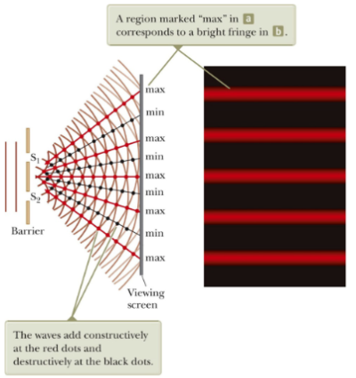
Thomas Young’s double-slit experiment in 1801 was a ground-breaking demonstration of this phenomenon. He allowed light to pass through two closely spaced slits, resulting in an interference pattern on a screen placed behind the slits. This pattern, characterized by alternating bright and dark bands (fringes), was a clear manifestation of light behaving as a wave. The bright fringes were a result of constructive interference, where the waves combined to amplify each other, while the dark fringes resulted from destructive interference, where the waves cancelled each other out.
Essential Conditions for Interference
For interference to manifest clearly, two primary conditions must be met:
- Coherence: The light sources must maintain a consistent phase relationship. This ensures that the peaks and troughs of the waves align consistently over time, producing a stable interference pattern.
- Monochromaticity: The light sources should emit waves of a single wavelength. This ensures uniformity in the interference pattern.
The Magic of Diffraction
Diffraction is another jewel in the crown of wave optics. It describes the bending of light waves around obstacles or the spreading of light waves as they pass through narrow openings. This phenomenon is a direct testament to the wave nature of light. If light were purely particle-like, it wouldn’t exhibit such behaviour.
Augustin-Jean Fresnel, a luminary in the 19th century, made significant contributions to our understanding of diffraction. His mathematical formulations and experiments provided a robust foundation for the wave theory of light.
In the context of Young’s double-slit experiment, diffraction ensures that light spreads out after passing through each slit, allowing the waves from the two slits to overlap and produce a diffraction pattern.
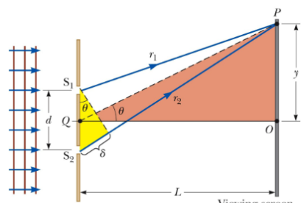
This was due to the difference in the paths travelled by light waves from the two slits. The path difference, denoted by , is given by the following, where is the distance between the slits: This assumes that the paths are parallel, which is a good approximation if is much greater than (), where is the distance between the double-slit setup and the observation plane/screen.
Interference Equations
Note that these are also often used for diffraction gratings, mentioned later For a bright fringe (constructive interference): Where:
- is the order number.
For a dark fringe (destructive interference): Where:
Using the large triangle in the [figure](Pasted image 20231010170613.png), the following equations can be derived from basic trigonometry: However, as these are small angles we can translate them into the following equations, in combination with the aforementioned equations: All of this information surrounding Young’s Double-Slit Experiment can allow us a method for measuring the wavelength of light - therefore giving the wave model of light credibility.
The Marvel of Diffraction Gratings
A diffraction grating is akin to the double-slit setup but includes multiple slits, often hundreds or thousands, spaced closely together. When light encounters a diffraction grating, it produces a complex interference pattern with multiple orders of bright fringes.
The historical roots of diffraction gratings trace back to the 17th century with James Gregory’s initial descriptions. However, their potential was truly realized in the 19th century by Joseph von Fraunhofer. His meticulous studies using diffraction gratings unlocked new avenues in spectroscopy, allowing scientists to dissect light into its constituent colours and study each one’s properties.
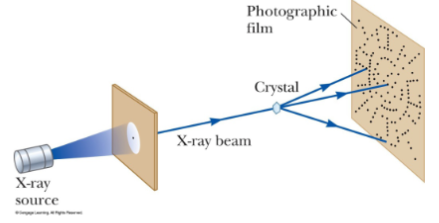
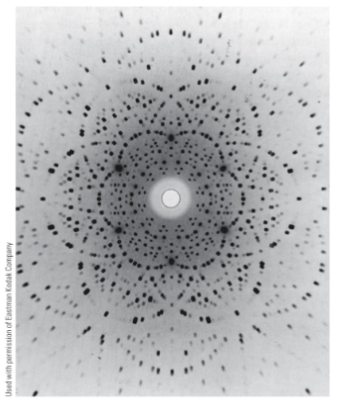
Interestingly, some very beautiful diffraction gratings are found naturally in crystals; crystals are essentially three-dimensional diffraction gratings, so create very complex patterns - this idea was first proposed by Max von Laue.
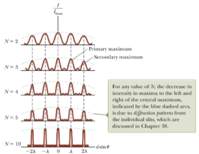
When more than two slits are used, the interference pattern displays both primary and secondary maxima: for slits, the primary maxima’s intensity is times that of a single slit. As the number of slits increases, the primary maxima become more intense and narrower, while the secondary maxima decrease in intensity relative to the primary maxima. The number of secondary maxima is , where is the number of slits.
Types of Diffraction Grating
- Transmission Grating: Made by cutting parallel grooves on a glass plate.
- Reflection Grating: Made by cutting parallel grooves on a reflective material.
Phase Changes in Electromagnetic Waves
Electromagnetic waves, like light, can undergo phase changes upon reflection. This behaviour is influenced by the refractive indices of the media involved.
- Reflection from Higher Index Medium:
- An electromagnetic wave undergoes a phase change of 180° upon reflection from a medium with a higher index of refraction than its original medium.
- This is analogous to a pulse on a string being reflected from a rigid support.
- Reflection from Lower Index Medium:
- There is no phase change when the wave reflects from a boundary leading to a medium with a lower index of refraction.
- This behaviour mirrors a pulse on a string reflecting from a free support.
Interference in Thin Films
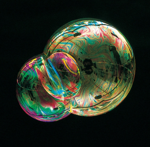
Thin films, such as those found in soap bubbles or oil on water, can produce vibrant colours when illuminated by white light. This is due to interference effects.
- Key Principles:
- A wave undergoes a 180° phase change on reflection when transitioning from a medium with refractive index to another medium with a higher refractive index .
- No phase change occurs if .
- The wavelength of light in a medium with refractive index is , where is the light’s wavelength in a vacuum.
- Constructive and Destructive Interference:
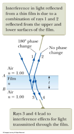
- Assuming light rays travel in air nearly normal to the film’s surfaces:
- Ray 1 undergoes a 180° phase change relative to the incident ray upon reflection.
- Ray 2, reflected from the film’s lower surface, undergoes no phase change and travels an additional distance of before the waves recombine.
- For constructive interference: , where .
- For destructive interference: , where .
- Assuming light rays travel in air nearly normal to the film’s surfaces:
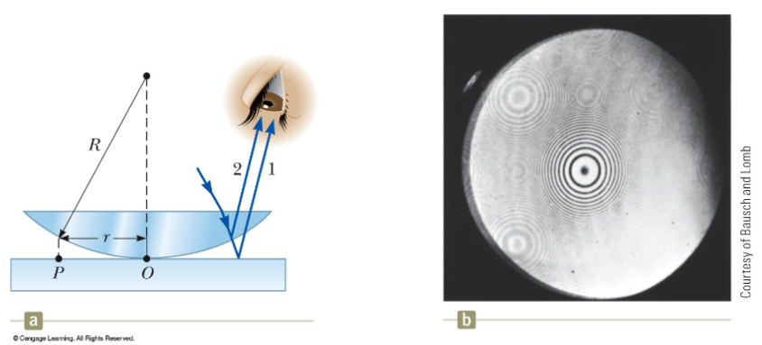
Newton’s Rings
Newton’s rings are an interference pattern observed when a plano-convex lens is placed on a flat glass surface. The varying air film thickness between the glass surfaces results in a pattern of light and dark rings.
-
Historical Context: Sir Isaac Newton first observed these rings, but the particle model of light he advocated couldn’t explain their origin. Later, the wave theory of light provided a satisfactory explanation.
-
Applications:
- Newton’s rings serve as a practical method to test the quality of optical lenses. If the rings are evenly spaced and circular, it indicates that the lens has a uniform curvature.
Resolution and Rayleigh’s Criterion
Resolution in optics refers to the ability of an imaging system to distinguish between closely spaced objects or features. This ability is crucial in various fields, from microscopy to astronomy, where distinguishing between minute details can provide valuable insights.
-
Resolved Images:
- When an imaging system can distinctly separate two closely spaced objects, they are said to be “resolved.” In such cases, each object appears as a separate entity, allowing for clear differentiation.
- This occurs when the sources are far enough apart to keep their central maxima from overlapping.
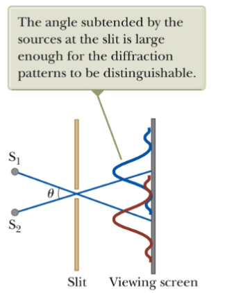 Example of a resolved image
-
Unresolved Images:
- If the imaging system cannot distinguish between two closely spaced objects, they appear as a single blurred entity. Such images are termed “unresolved.” This blurring can be due to the system’s inherent limitations or external factors like atmospheric interference.
- This occurs when the sources are too close together and the two central maxima overlap.
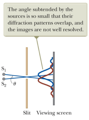 Example of an unresolved image
-
Rayleigh’s Criterion:
- Lord Rayleigh, a British scientist, provided a quantitative measure for resolution, especially in the context of diffraction patterns. According to Rayleigh’s criterion, two point sources are just resolvable (distinguishable) when the center of the diffraction pattern (central maximum) of one coincides with the first minimum of the other. This is also called the limiting condition of resolution:
- Mathematically, for a circular aperture (like a telescope), the angular resolution is given by: Where is the wavelength of light being used, and is the diameter of the aperture. The diffraction pattern of this aperture consists of a central bright disk surrounded by progressively fainter bright and dark rings.
- This criterion has been fundamental in designing optical instruments, ensuring they achieve the desired resolution.
-
Historical Context:
- The study of resolution and the establishment of Rayleigh’s criterion have played pivotal roles in advancing optical sciences. It has guided the development of instruments like telescopes and microscopes, pushing the boundaries of what we can observe, from distant galaxies to minute biological structures.
Polarization: Unveiling Light’s Orientation
Every light wave oscillates in a particular direction. This direction of oscillation is termed polarization. The discovery of polarization added another layer of complexity to our understanding of light, reinforcing its wave-like properties.
Étienne-Louis Malus’s experiments in 1808 were pivotal in this domain. He discovered that when light reflects off certain surfaces, it becomes polarized, meaning its waves oscillate predominantly in a single direction.
Polarization by Selective Absorption
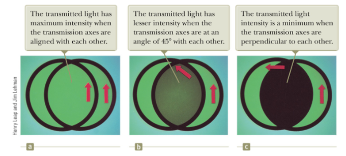
One common, if not the most common, method to achieve polarization is through selective absorption. Materials like Polaroid, discovered by E. H. Land, are designed to transmit light waves oscillating in one direction while absorbing those oscillating in perpendicular directions. This has led to a plethora of applications, from glare-reducing sunglasses to advanced optical instruments.
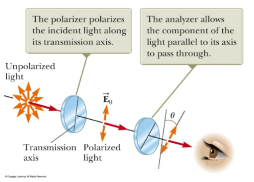
In an ideal polarizer,
- All light with the electric field parallel to the transmission axis is transmitted.
- All light with the electric field perpendicular to the transmission axis is absorbed.
Intensity Modulation and Malus’s Law
When polarized light encounters another polarizing filter (the analyser), its intensity can be modulated based on the alignment of the filter; leading to applications like LCD screens. This behaviour is mathematically described by Malus’s law: , where is the initial intensity of the light and is the angle between the light’s polarization direction and the axis of the filter.